CAD FOR MACHINE DESIGN

Fast-track designs from concept to customer

Increase design development agility and get your best ideas to market efficiently with Autodesk software for machine design.

Designer and engineer standing in shop, looking at illustrated outline of machine CAD model

What could you create with 20 to 70% more engineering time?

The traditionally careful pace of change in manufacturing is being disrupted by market fluctuations, supply chain issues, and skills shortages. Machine and equipment companies are adopting new approaches to increase design agility, create capacity for innovation, and deliver new value to customers amid the chaos.

Learn how leading machine design companies drive efficiency by adopting connected and integrated machine design software.

Transform your business with CAD for machine design

Innovate at speed

Reduce risk while fast-tracking machine designs from prototype to product with tools that help you respond rapidly to customer insights and stakeholder feedback.

Proceed with trusted data

Make well-informed decisions earlier during the design phase to accelerate your ideas, eliminate the disconnect with manufacturing, and improve time to market.

Unlock new possibilities

Leverage automation and collaboration tools to create innovation capacity, so you can transform insights into smarter products and diversified offerings.

Ensure responsible development

Stand out from the competition by embedding sustainability into every decision you make. Gather feedback on your designs’ impact from the earliest stages of development.

How top manufacturers drive growth with machine design software

Enhance your process with CAD for machine design

Mechanical design

Automate your machine design process with advanced mechanical design software. Free up design time, reduce barriers to collaboration, and boost your capacity for innovation.

Design automation

Empower your design and engineering teams to concentrate on groundbreaking solutions by using automation to minimize errors and time spent on repetitive tasks. Scale your development processes for seamless execution.

Simulation

Venture into unchartered territories confidently with precise and reliable analysis. Leverage simulation tools to make data-driven decisions, fine-tune your designs, and get the best solution to market efficiently.

Manufacturing process automation

Connect disciplines using common CAD models to program CNC machines. Design fixtures and create toolpaths before engineering data is released—any changes automatically update computer-aided manufacturing (CAM) workflows.

Factory floor design

Minimize risk and maximize efficiency during system integration with large-scale design projects. Point cloud scanning, clash detection, and installation sequencing help you make more informed decisions at every step.

Product lifecycle management (PLM)

Connect your colleagues, clients, and supply chain with a single, secure data model. Always know who’s responsible for the next step in your design cycle, and automatically maintain an audit trail of decisions and their impact.

Design for manufacture

Reduce design cycle time with integrated design for manufacturing and assembly (DFmA) technology. Real-time feedback helps optimize designs for manufacturing with reduced feedback cycles.

Manufacturing documentation

Improve time to market by accelerating downstream processes. Automate manufacturing data preparation with bill of materials (BOM), nesting, and CAM in a single environment.

Model-based definition

Use your 3D CAD model as the single source of truth containing all product manufacturing information (PMI). Reduce the need for manual drawing creation, speed up the design cycle, and improve manufacturing collaboration.

Machine design software

Get Inventor + AutoCAD + Autodesk Fusion + more—Professional-grade tools for product development and manufacturing planning.


Professional-grade product design and engineering tools for 3D mechanical design, simulation, visualization, and documentation.


Cloud-based 3D CAD / CAM / CAE / PCB software for product design.


Stay up to date on machine design best practices

alt text

E-BOOK

Gain agility by automating busywork

Free up your time to focus on projects where you add unique value. Learn how iLogic technology, found in Autodesk Inventor, helps engineers automate routine tasks, accelerate product configuration, and improve time to market.


alt text

Webinars

Watch design and engineering webinars

Learn from Autodesk experts how CAD for machine design can help you anticipate manufacturing innovations, collaborate efficiently, and explore more design options. View our extensive library of webinars for designers and engineers.


e-book

Increase the value of your design data

The need for more agility in design–and in the entire development process–requires a modern modeling approach. Learn how you can easily incorporate design changes, get more value from your models, and reuse existing design data by modeling in parametric 3D.


Drive growth–ahead of your competition–with Autodesk

Talk to a sales representative about how Autodesk design and manufacturing solutions can help you create breakthrough innovations.

Frequently asked questions (FAQ) about CAD for machine design

What is a machine?

Machines are physical systems that convert power into action. Examples of simple machines are the wedge, the lever, and the pulley. Complex machines have many parts that work together, including mechanical, electrical, and electronic components. Many modern machines are computer controlled and are programmed and monitored using a software interface.

What is machine design?

Machine design is the process of imagining and creating physical systems that meet the needs of customers in industries such as energy, aerospace, automotive, agriculture, marine, and manufacturing.


The machine design process includes understanding the physics needed to transform power into action to complete the intended task, planning component interactions, ensuring proper fit within design constraints, and specifying materials while considering project timelines and profit margin.


Technical drawings and 3D computer-aided designs (CAD) models are typically created to communicate and review the design and to coordinate the design process among stakeholders.


The final output of the machine design process is the information required to make, commission, and service the design, and may include technical drawings, a written specification, and a bill of materials (BOM).

Jobs in machine design could include industrial designer; mechanical, electrical, or electronic engineer; simulation specialist; CAD designer; and CAD drafter.

What do machine designers do?

Machine designers use mathematical principles, engineering physics, industry knowledge, and specialist software to address customer problems and develop an idea for a machine from its conceptual stage to a detailed design.


The detailed design must meet customer requirements and be delivered profitably. The design is communicated to stakeholders such as customers, manufacturing, and procurement via a computer-aided design (CAD) model, technical drawings, a bill of materials (BOM), and a specification.


Machine design is collaborative and can include multiple disciplines including industrial design and mechanical, electrical, and electronic engineering, and also includes feedback from customers, suppliers, manufacturing specialists, and project management teams.

What is the machine design process?

The design engineering process is crucial for successful machine design businesses. The objective of design development is to imagine and agree on a machine that benefits both customers and the business. Design development is constrained by budget, engineering capacity, and time to market.


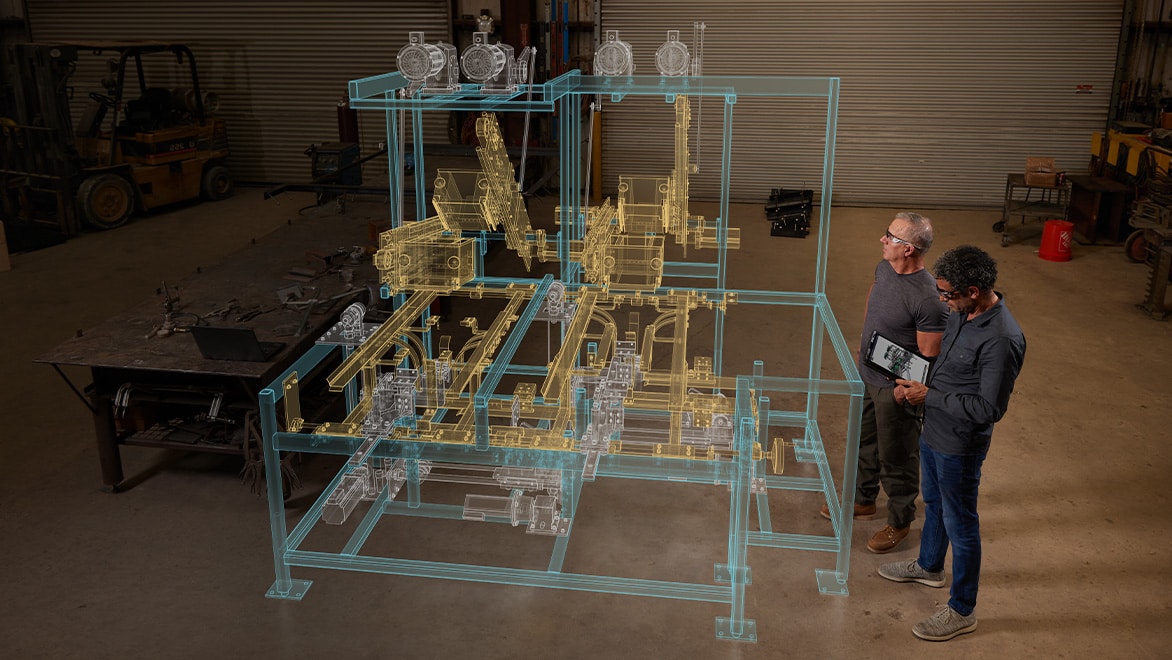
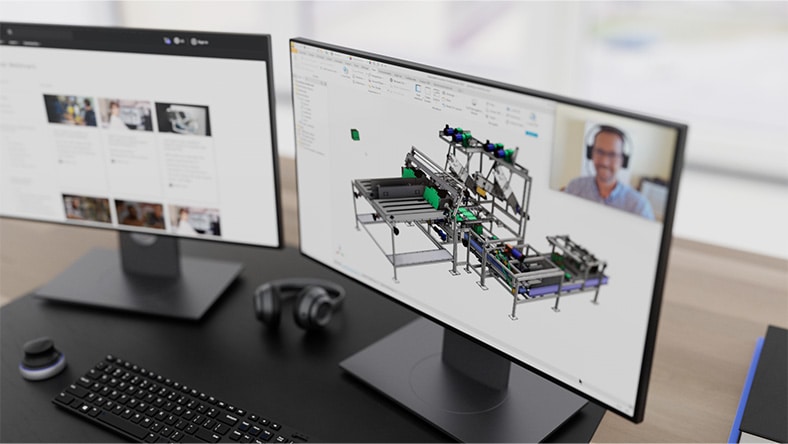
The machine design process is collaborative and may involve specialists in disciplines such as industrial design, mechanical, electrical, and electronic engineering working together. Feedback can be included from stakeholders such as customers, project management, procurement, manufacturing, installation, and servicing.


The machine design process is iterative and cyclical, with ideas undergoing multiple rounds of prototyping, testing, evaluation, and review until the final design is considered optimal and reliable enough for production.


The machine design process starts by defining the problem, then brainstorming potential solutions before creating prototypes, testing them, gathering feedback, and evaluating whether the problem statement can be further refined, whether to reject or accept the proposed solutions, or whether the solutions can be improved with another development cycle.

What is machine design software?

Machine design software helps designers by automating tasks, tracking processes, and enabling collaboration among designers and stakeholders such as project management, procurement, manufacturing, or customers.


Examples of machine design software include 3D computer-aided design (CAD) software, which designers use to create virtual models of their designs to help calculate the physics of the design or to ensure that moving components won’t clash. This saves time in prototype creation. Additionally, technical drawings can be created from the 3D CAD model, reducing the time it takes to document and communicate the design.


Computer-aided engineering (CAE) software helps designers to create simulation studies that automate the calculation of stress, fluid flow, thermal dynamics, and vibration, which saves time in physical prototype testing.


The increased accessibility of cloud-based data management is accelerating the use of model-based definition (MBD), or the use of the 3D CAD model to drive downstream manufacturing processes, reducing the need for technical drawings.

Which software is used to design machines?

Software to design machines can include:

  • Computer-aided design (CAD): 3D CAD is used to create virtual models of mechanical, electrical, or electronic components and their relationships. Technical drawings and a bill of materials (BOM) are automatically generated from the 3D model.
  • MCAD: This refers to CAD software that is specifically optimized for mechanical design, including tools to design mechanical elements such as shafts, gears, springs, cams, belts, bolted connections, and structural frames.
  • ECAD: ECAD software is specifically optimized for electronic or printed circuit board (PCB) design, including schematics, 2D trace layout, and 3D modeling.
  • Visualization: Visualization software is used to create computer-generated imagery (CGI) or digital renderings of designs to help communicate the design to customers or partners. Renderings can be photorealistic still images or animations showing how the design is assembled or operates.
    • Virtual reality (VR) or augmented reality (AR) software and hardware can be used to allow humans to interact directly with CGI to help visualize the design, or to train operators in a safe environment.
    • Digital twin augments the CGI with data from sensors embedded in the machine to optimize the maintenance and operation of the machine and its supporting services.
  • Computer-aided engineering (CAE): CAE or simulation software is used to analyze the performance of a design. Examples include finite element analysis (FEA), used to simulate stress, or computational fluid dynamics (CFD), used to simulate the flow of liquids and gases.
  • Tolerance analysis: Tolerance analysis is used to automate the calculation of tolerance stackups and optimize tolerances to ensure the feasibility of interchangeable parts while minimizing the cost of manufacture.
  • Generative design: Generative design is a unique approach that differs from simulation, or lightweighting. While simulation uses a 3D CAD model of a component to analyze the effects of stress on the design, generative design works the opposite way. The designer sets constraints, such as physical loads, materials, and manufacturing methods, and generative design generates multiple models of viable components that meet the performance criteria. The designer can then eliminate design options based on factors such as weight, safety factor, cost, or aesthetics, finally selecting their preferred design from the options remaining.

What CAD software does Autodesk provide for machine design?

Autodesk empowers innovators with Design and Make technology for product design and engineering, equipping machine designers to work fluidly across boundaries of project, discipline, and industry.


Autodesk software for machine design includes:

  • The Product Design and Manufacturing Collection which includes:
    • Autodesk Inventor Professional-grade product design and engineering tools for 3D mechanical design, simulation, visualization, and documentation.
    • Inventor Nastran CAD-embedded software for non-linear stress, thermal, vibration and fatigue simulation.
    • Inventor Tolerance Analysis Tolerance stackup analysis software for evaluating the impact of dimensional variation.
    • Inventor Nesting True shape nesting software for Inventor to optimize yield from raw material.
    • Inventor CAM Integrated 2.5- to 5-axis CAD/CAM programming solution for Inventor.
    • Vault Product data management software to manage design files.
    • AutoCAD 2D and 3D CAD software with industry-specific toolsets.
    • Factory Design Utilities Factory design software to plan, design and install an efficient production layout.
    • Navisworks Large-scale design review software with clash detection and scheduling.
    • ReCap Pro Reality capture and 3D scanning software and services.
    • 3Ds Max 3D rendering and animation software for design visualization.
    • Fusion 360 Cloud-based CAD/CAM/CAE software for product design and manufacturing.
    • Fusion 360 Manage with Upchain Cloud PLM and PDM that easily connects your data, people, and processes.
    • Design Review Design Review CAD viewer software lets you view, mark up, print and track changes to 2D and 3D files for free—without the original design software.

What software is used for mechanical drawing?

Mechanical drawings are technical drawings created to communicate design intent, diagram processes, calculate folded sheet metal flat patterns, optimize fabrication with nesting, or provide instruction for installation and maintenance. Mechanical drawings are created by design software that falls into the computer-aided design (CAD) category.

  • CAD software like Autodesk AutoCAD automates the traditional process of 2D technical drawings, with tools such as copy and paste, blocks, and the sheet set manager.
  • CAD software like Autodesk Inventor takes drawing automation a step further, by generating mechanical drawings directly from a 3D CAD model created by the designer. This can speed up the process of mechanical drawing creation and ensures that any updates to the design are automatically reflected in every drawing that references the model.
  • CAD software like Autodesk Fusion 360 brings together design, engineering, electronics, and manufacturing software all in one —connecting the entire product development process into one integrated, cloud-based software including 3D CAD, CAM, CAE, and PCB.

What is the best mechanical design software?

The best mechanical design software is computer-aided design that has been optimized for the mechanical design process (MCAD). When evaluating MCAD software, look out for the following:

  • 3D modeling of parts and assemblies to conceptualize the physical dimensions and spatial relationships of the design
  • Extendable libraries of mechanical and electrical components such as nuts, bolts, washers, O-rings, bearings, keys, cogs, belts, and springs
  • Mechanical design accelerators to automate the design and modeling of items such as bolted connections, shafts, cams, and pulley systems
  • Specific tool sets that automate the design and modeling of sheet metal components, structural frames, PCBs, cable harnesses, piping runs, and plastic enclosures
  • The ability to use CAD models to assess designs for physical properties such as stress, thermal, vibration, and fluid flow
  • The ability to implement model-based design (MBD) with tools for model-based annotation (MBA), geometric dimensioning and tolerancing (GD&T) and tolerance stack-up analysi
  • Visualization tools to create computer-generated imagery (CGI) for communication, sales, and marketing, including photorealistic renderings, and animated videos
  • The ability to collaborate by securely sharing designs for feedback, review, and sign-off
  • The ability to collaborate on a shared CAD model with specialists in other industries, such as structural design, civil design, or BIM
  • The ability to use the CAD model for manufacturing preparation tasks like manufacturing drawings, bill of materials (BOM) creation, sheet metal nesting, and CNC programming
  • Integrated product data management (PDM) to securely manage files with permission controls, a release process, and engineering change orders

How does machine design software benefit businesses and professionals?

Businesses that manufacture machines as products feel the pressure of providing innovative solutions to meet customer demands and releasing them to market before their competition can.


The key to successful machine development lies in design engineering, which ensures that the machines not only meet customer needs but also generate profit for the business.


The decisions made during design development can affect the quality, components, materials, manufacturing processes, and usability of the machine over its lifecycle.


Machine design software like computer-aided design (CAD) and computer-aided engineering (CAE) benefit businesses and professionals by automating design processes and managing data insights, enabling designers and engineers to make timely and effective decisions that increase the success of the product, aiding operational efficiency, and improving time to market.

What is CAD used for in manufacturing?

Computer-aided design software (CAD) is used at multiple points in the manufacturing process.


During the design phase, CAD designs are shared with the manufacturing team to assess the design for manufacturing and assembly (DfMA). Feedback from the manufacturing team can be incorporated into the design, helping the design be more efficient, and therefore more profitable, to manufacture.


When design development is complete, designs are released for manufacture. CAD is used by the manufacturing team in the design of jigs, fixtures, and “stop-go” devices for quality control.


Computer-aided manufacturing (CAM) uses the 3D CAD model for computer numerical control (CNC) programming, which automates the movements of manufacturing machinery. The convergence of CAD and CAM allows CNC programming to take place using the same software as CAD, with the advantage that changes to the CAD model automatically update CAM toolpaths.


After components are made, CAD data and CAM data are used together for computer-aided inspection (CAI) and quality control. The manufactured component is compared to the CAD model using metrology devices to assess compliance with the specified tolerances and surface finishes.

See more FAQ