& Construction

Integrated BIM tools, including Revit, AutoCAD, and Civil 3D
& Manufacturing

Professional CAD/CAM tools built on Inventor and AutoCAD
Image courtesy of Disney
See how Autodesk’s Design and Make Platform enables creative problem solvers to build limitless galaxies—here and far, far away.
Circuit design is the first step for every electronics design project. This requires the creation of a schematic diagram that defines how electronic components are logically connected on a printed circuit board (PCB).
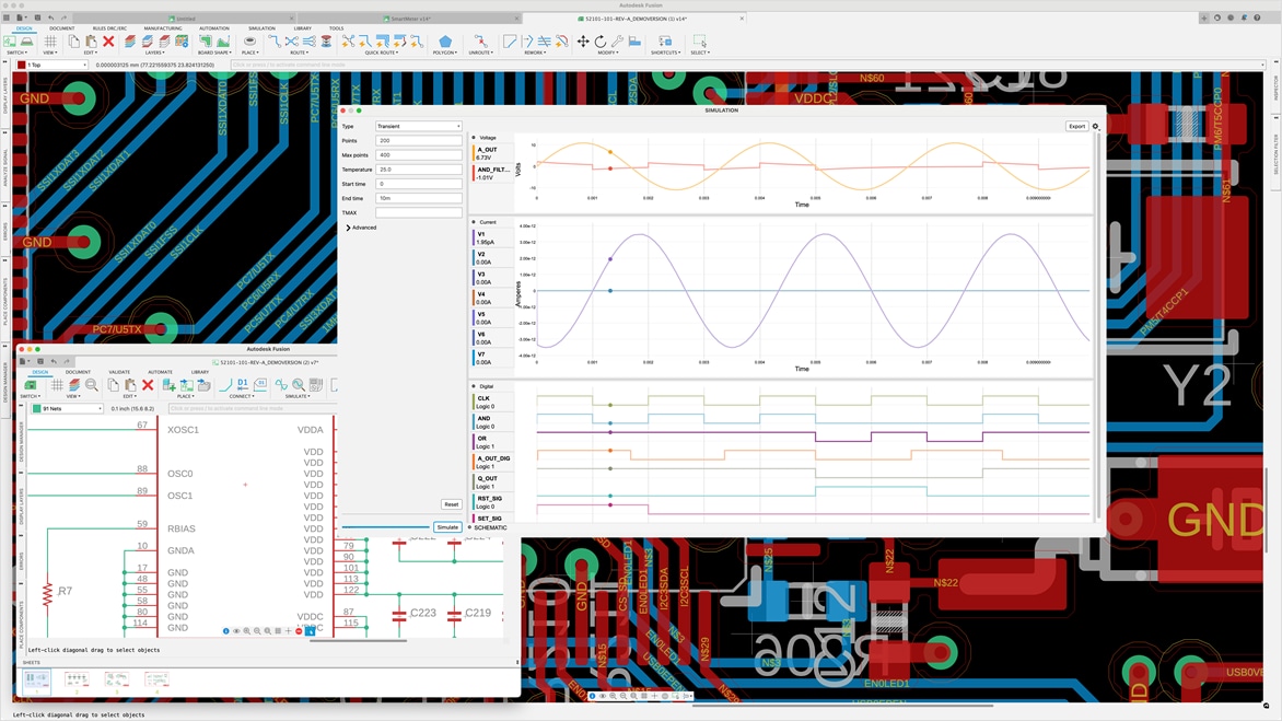
Engineers can perform SPICE simulations or translate their completed schematic into the PCB design workspace.
In electronics, there are two types of circuit design - analog and digital. Analog circuits deal with continuous signals and often involve amplification and filtering, while digital circuits deal with discrete signals, performing operations like arithmetic and data manipulation.
Using multiple tools for your electronics circuit design needs is inefficient. Autodesk Fusion is an all-in-one solution for circuit design to seamlessly design, test, and simulate circuits. Simplify the process of creating complex circuit designs with an intuitive, user-friendly interface.
With the real-time collaboration features, you can work with your team from anywhere in the world. Whether designing a simple circuit or a complex system, Fusion has all the tools to bring your ideas to life.
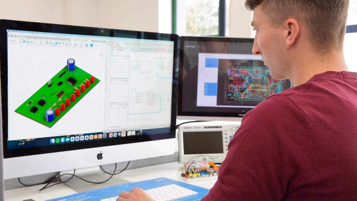
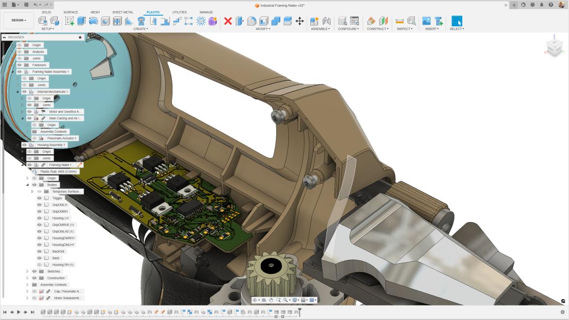
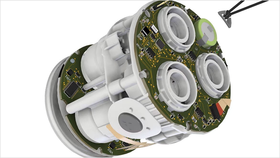
Product designers require solutions that help them bring consumer products to market faster and to easily transition from design to production. Autodesk Fusion enables seamless integration of 3D design and electronics circuit design.
The advanced circuit design tools in Fusion include real-time design validation, 3D visualization, and simulation capabilities, making it easy to go from design to manufacture.
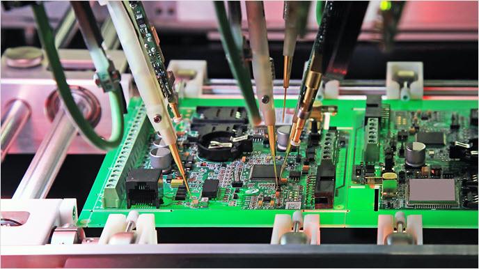
Fusion includes simulation capabilities that allow you to test your design and identify potential issues before building the circuit.
Fusion electronics provides an extensive repository of components. Partners such as Ultra Librarian and SnapEDA have created Fusion add-ins to help you quickly build your components.
Fusion electronics can export designs in various standard formats such as Gerber, ODB++, including Ansys export for simulations and analysis.
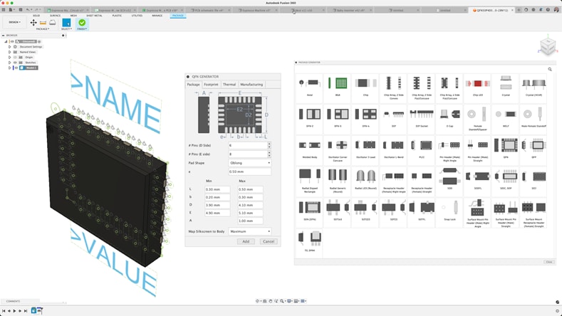
Autodesk's library editor package generator includes all IPC-compliant template calculators that generate your footprint and 3D model moments after inserting component details.
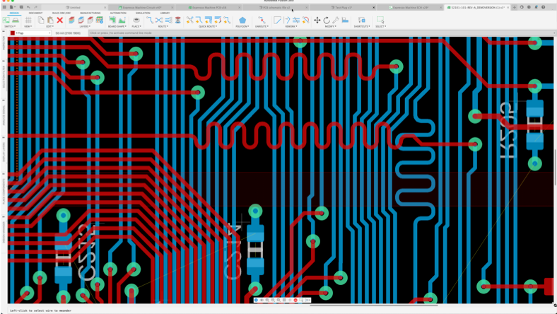
Fusion electronic routing capabilities offer a range of powerful tools that make it easy to create complex PCB layouts with precision and efficiency. Live DRC, quick route, group route, auto-complete, and violator modes are vital features to help you finish projects sooner.
The electronics sharing feature in Fusion allows users to collaborate in real-time on electronic design projects. The software includes tools for sharing and reviewing designs, as well as for tracking changes and revisions.
Explore the utilization of design automation and modular design blocks, providing real-world examples to illustrate their effectiveness in circuit design workflows.
The ECAD/MCAD workflows in Fusion effectively integrate electronics and mechanical workflows into a single solution. Design changes can quickly be adopted because there’s no need for file conversions or translations. Modifications to the circuit board in the assembly design workspace will be applied to the PCB workspace.
This free version for hobbyists and makers includes 2 schematic sheets, 2 signal layers, and 80-cm2 board area.
We offer free circuit design software for students and educators around the world.
Circuits empower you to bring your ideas to life with free, easy-to-use online tools.
The printed circuit board (PCB) layout brings your circuit design to life in its physical form. Learn more about the PCB layout process and how to design your own.
The schematic design defines connectivity between your electrical component symbols. Learn more about the schematic design process and how to design your own.
SPICE simulation allows you to analyze voltage and current performance in your circuit design. Learn more about SPICE and how to run your first SPICE simulation.
Electronic circuit design involves ideation, creation, and revision. Learn about PCB design and the circuit design process.
Learn how to make your first high-speed PCB design a success by minimizing crosstalk, EMI, and more.
Learn how Autodesk Fusion provides you with the necessary routing tools and environment settings to make interactive routing easy and efficient.
Use these top 10 PCB routing tips to make your first PCB layout a success.
Learn how to design your printed circuit board (PCB) layout with these tips for routing, component placement, heat dissipation, and more.
By simulating the flow of air, heat transfer, and other factors, identify potential issues and optimize designs for maximum efficiency.
Searching for the correct circuit board design software can be daunting. Remembering that circuit board design is one step in developing product solutions. This evolving step must collaborate with many other engineering disciplines, especially mechanical engineers. You need to be able to design and create high-quality designs and streamline your workflow with the right software. A solution that requires no file conversion with seamless electromechanical capabilities, integrated versioning, and collaboration features are crucial. That allows you to work with different team members, access your design from anywhere and track changes easily. In addition, you want software that is easy to use and navigate so that you can focus on the design process. Autodesk Fusion is a great solution!
Autodesk Fusion electronics is circuit design software. Subscribe to affordable monthly or annual options, starting as low as
Yes, Fusion includes simulation capabilities that allow you to test your design and identify potential issues before building the circuit board.
Autodesk Fusion includes a modern, collaborative environment to connect teams and stakeholders. You'll gain the ability to:
Yes, Autodesk Fusion electronic circuit design software is easy to learn. It includes a user-friendly interface, access to self-paced learning, product documentation, and in-product learning content.
If you're currently working with EAGLE design or libraries, importing will not be necessary because Fusion electronics is 100% compatible with fusion. You can decide to upload them or simply open them in Fusion and continue to work. For further detail consult the Migration guide we have made available.
Circuit design software is a tool that engineers use to design and test electronic and electrical circuits. It allows for the creation of schematic diagrams where the components of a circuit can be represented using symbols, and their connections can be mapped out.
Designing a circuit involves several steps. Here's a general overview of the process:
1. Define the purpose of the circuit: Understand what the circuit is supposed to do. This includes knowing the inputs and desired outputs.
2. Design the circuit schematic: Based on the requirements, start designing the circuit on paper or using a circuit design software. This involves selecting the right components (like resistors, capacitors, transistors, etc.) and connecting them correctly.
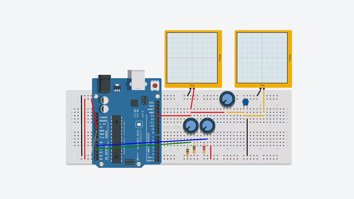
3. Simulate the circuit: Using circuit simulation software like Autodesk Fusion, validate that your circuit works as intended. This step can help you identify and fix potential issues without having to build a physical circuit.
4. Create a PCB layout: Once your schematic design is finalized and simulated, you can proceed to design the Printed Circuit Board (PCB). This involves deciding where each component will go on the board and how they will be connected.
5. Fabricate the PCB: After finalizing the PCB layout, you can have the PCB manufactured. This process involves etching the copper layers to create the necessary pathways for electricity, and drilling holes for component leads.
6. Assemble and test the circuit: Once the PCB is ready, solder all the components onto the board following the layout. After assembly, test the circuit to ensure that it functions as expected.
Throughout this process, you may need to iterate on your design several times to get the desired results. Circuit design software like Autodesk Fusion can be very helpful in this process, allowing you to design both the schematic and the PCB layout, and even providing tools for circuit simulation.
