Electronic Schematics Software

Electronic schematic design is critical for efficient workflow, allowing engineers to innovate solutions rather than tool complexity.

Man using Autodesk Fusion, electronic schematic software.

What is electronics schematics software?

Electronic schematic software, also known as electric design automation (EDA) software or electrical CAD (ECAD) software, is used to create and document electrical circuit schematics. Electrical schematic software allows designers and engineers to design the logical representation of their design. It helps them visualize and analyze electrical circuits, ultimately making it easier to develop and communicate complex electrical designs efficiently and accurately.

Electronics design and drawings

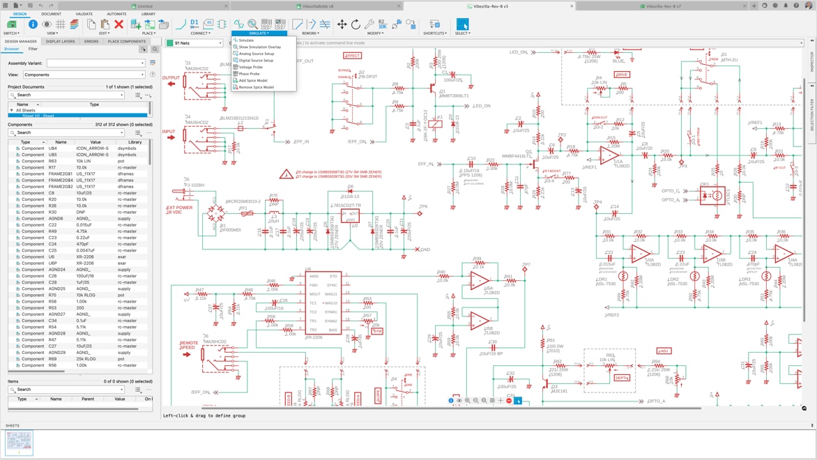
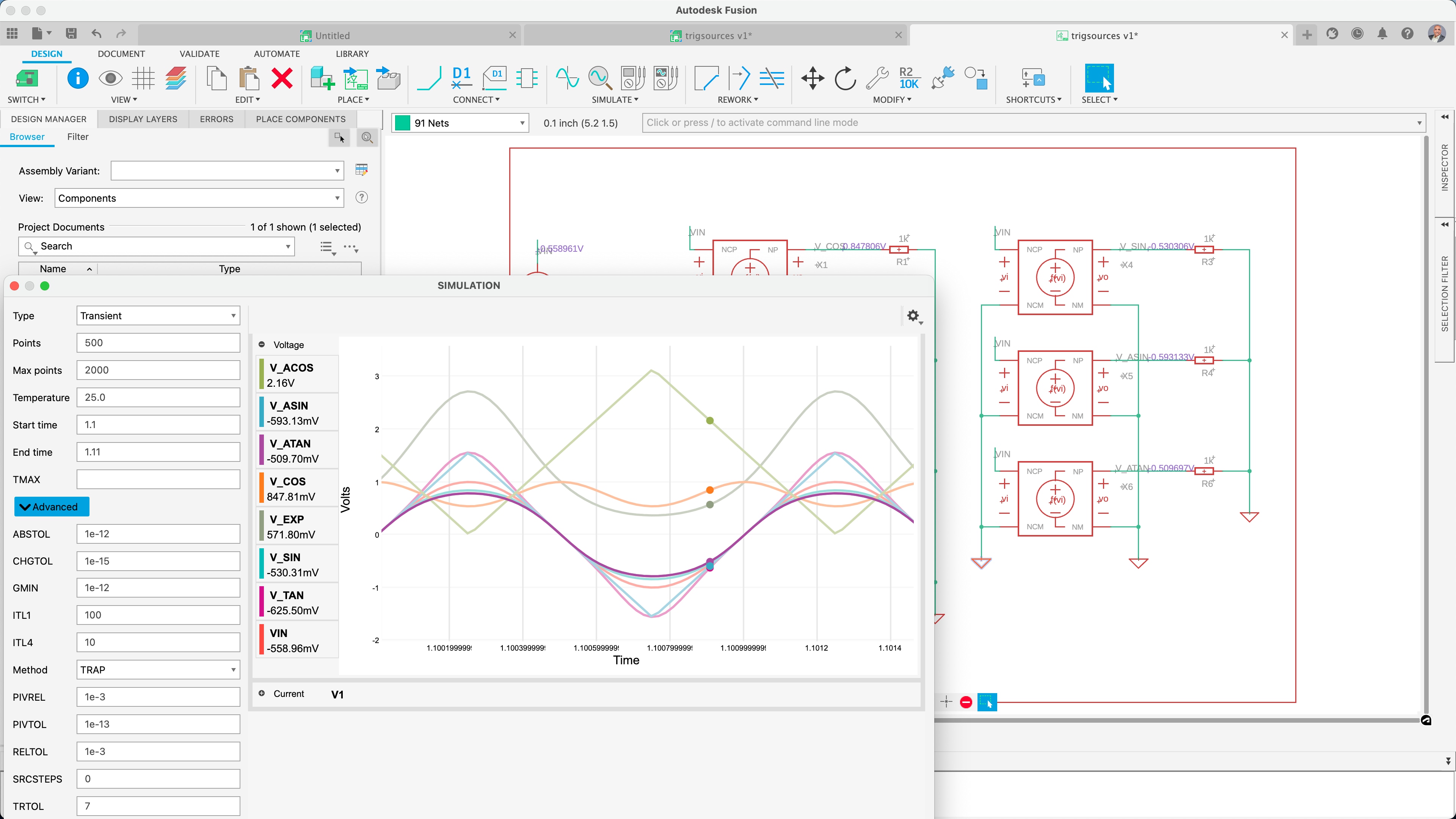
Electronic schematic design is fundamental to creating consumer products, serving as the technical backbone that ensures functionality, reliability, and manufacturability. This design phase delineates electronic concepts into clear, actionable diagrams, guides the selection of components, facilitates accurate simulations, and streamlines troubleshooting.

At this stage, it is ideal for adhering to industry standards, simplifying the production process, and providing a definitive reference throughout the product's lifecycle. Ultimately influencing the product's market performance and compliance with industry standards.

A Spice Simulation of a schematic of the results of and signal input being amplified by an OpAMP

Different types of electronic schematics

Electronic schematic designs vary to cater to different functionalities and complexities within consumer electronics. For instance, a block diagram provides an overview of the system, outlining the key components and their interactions, ideal for initial design conceptualization. Circuit diagrams, with detailed representations of the electronic components and their interconnections, are used for the hands-on construction and troubleshooting of circuits.

Benefits of electronic schematics software

Efficiency and speed

Electronic schematic design is the critical roadmap that makes sure every electronic product functions as intended. It streamlines development from conceptualization to final production while maintaining industry compliance and operational integrity.


Electronic symbols and notation

Adopting standardized symbols and components in schematic designs guarantees uniformity and adherence to industry standards. Simplifying the process of understanding and interpreting complex schematics enhances engineering workflows' efficiency and accuracy.


Scalability for complex designs

Electrical schematic software like Autodesk Fusion includes simulation tools that allow users to validate and test electrical circuits to identify errors, conflicts, and performance issues early in the design process. This approach significantly reduces the rework potential and optimizes time to market.


Electronic schematics software features

Autodesk Fusion component library.

Library of components

Autodesk Fusion library editor with SPICE model mapping capabilities is crucial. It ensures accurate and efficient simulation of electronic circuits, enabling verification and precision in developing technological solutions.

Schematic spice simulation in Autodesk Fusion.

Schematic spice simulation

Autodesk Fusion's schematic editing interface and SPICE simulation integration offer a comprehensive solution for electronic circuit design intended to verify expected value results. Resulting in less rework and streamlining time to market.

How to convert a schematic to a PCB with only one click

PCB design tool integration

Autodesk Fusion's innovative one-click conversion from schematics to layout, preserving annotations, guarantees designers accurate synchronization, and component selection. Any updates to the schematic are instantaneously applied in the PCB layout.


Collaboration features in Autodesk Fusion.

Sharing and collaboration

Working on electronic schematics within a collaborative environment is essential for harnessing collective expertise and innovation. It significantly elevating the quality and ingenuity of product design in today's fast-paced industry.


Autodesk electronic schematics software

Cloud-based 3D CAD / CAM / CAE / PCB software for product design.


Optimize PCB design electromagnetic performance by controlling the impedance of every critical transmission line.


Electronic schematics resources

The schematic forms the building block of every electrical circuit, and even if you aren’t designing one yourself, knowing how to read one is invaluable.


Ready for that next great idea for a PCB project? It all starts with your schematic design. Get started with these tips.


Easily pint a schematic in Autodesk Fusion electronics by following these simple steps.


Electronic schematics software frequently asked questions (FAQ)

Can electronic schematics software be used for professional-grade projects?

Yes, electronics schematic software can be used for professional-grade projects. Many professionals in the electronics industry rely on such software for designing and documenting complex electronic circuits. These tools offer a range of features that make the design process more efficient and accurate. Some key features include schematic capture, component libraries, simulation, PCB layout integration, and Design Rule Checking (DRC).

What is the best electronic schematics software for beginners?

Autodesk Fusion is a great electronics schematics software choice for beginners. With Fusion, you'll gain access to comprehensive electronics and PCB design tools in one product development solution.

Is it necessary to have a background in electrical engineering to use electronic schematics software?

No, it is not necessary to have a background in electrical engineering to use electronic schematic software. Autodesk Fusion is user-friendly and has an intuitive interface that makes it accessible to individuals without formal electrical engineering training.

Can electronic schematics software help me simulate my designs?

Yes, many electronic schematic software tools come with simulation capabilities that allow you to simulate and analyze the behavior of your circuit designs before physically building them. Simulation is a valuable feature that can help you identify potential issues, validate your design, and optimize performance. Learn how Autodesk Fusion can help.

What is the difference between an electronic schematic and a wiring diagram?

Electronic schematics and wiring diagrams serve different purposes in the field of electrical and electronic design, even though they may look somewhat similar. An electronic schematic is a representation of an electrical circuit using symbols for components and lines to show the connections between them. It is a detailed diagram that provides information about the components, their values, and the relationships between them in a circuit. Schematics are used for circuit design, analysis, and documentation. A wiring diagram, on the other hand, focuses specifically on the physical layout of wires and connections between components. It shows how the components are physically connected, often with more emphasis on the routing of wires and cables. Wiring diagrams are typically used for installation and troubleshooting.

Why are electronic schematics important?

Electronic schematics are crucial in the field of electronics for many reasons including:

  • Design and planning
  • Documentation
  • Communication
  • Analysis and troubleshooting
  • Simulation
  • Integration with PCB design
  • Compliance
  • Collaboration
See more FAQ