Trace length and high-speed PCB designs go hand-in-hand. This ultimate guide will provide all the details you need to know and how to leverage the Fusion 360 Electronics Signal Integrity Extension to get it right the first time.
Trace Length and High-Speed PCB Designs
High-speed PCB design requires special considerations to get a functioning design – one being trace length. Ensuring that signals arrive in time to process means that trace lengths may need to match.
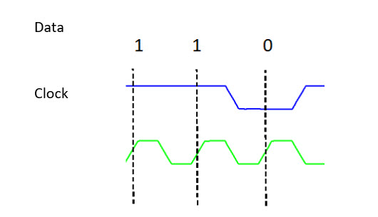
Digital information synchronizes to a clock signal. On either the rising or falling edge (and sometimes even both) data is “clocked” into a circuit. Consider the example below where data 110 is in blue and the clock is in green.
Data clocks on the rising edge of the clock (lower signal in green)
If the clock or data signals delay by more than one clock on time, erroneous data (101) reads.
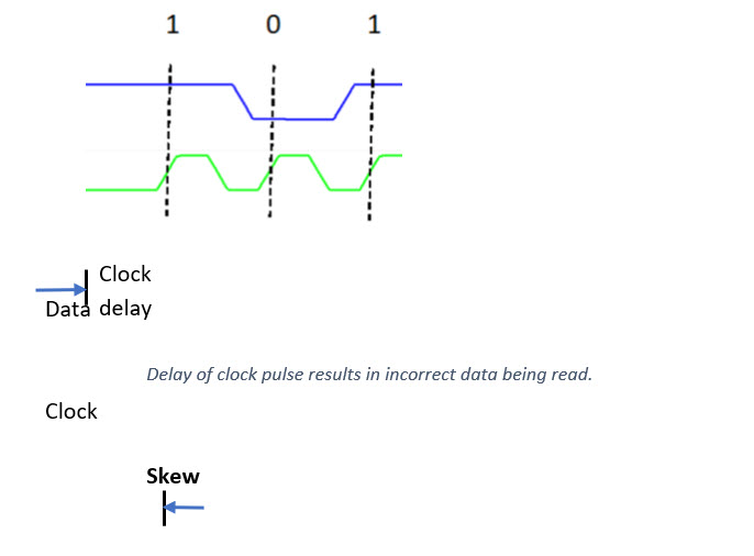
What is a Skew?
Skew is a measure of the difference in time between two signals. Often skew between a clock signal and the data it references must be less than a 1/10 the clock period. This ensures that the clock edges used clock-in the correct data. You sometimes define Skew in terms of UI or Unit Interval. Unit Interval is the minimum time for one bit to transition. For example, many manufacturers of HDMI ICs recommend 0.15 UI for HDMI signals for boards using their ICs.
Skews occur because of uneven trace lengths. Thus, it is also sometimes the maximum allowable difference in length between two related traces. You will see this measurement for skew with many USB ICs where the skew specifies as a maximum of 5 mil.
Skew can be defined as a differential pair (intra-pair) or be defined between related differential pairs (inter-pair).
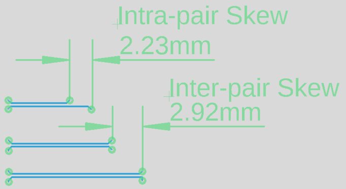
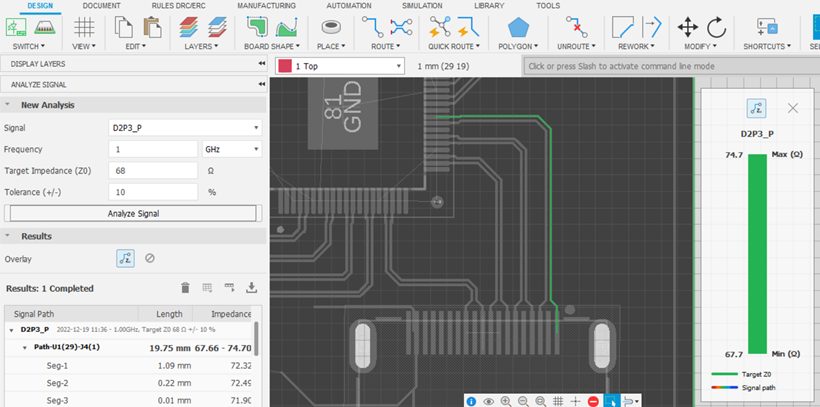
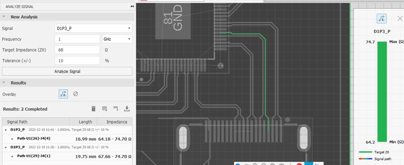
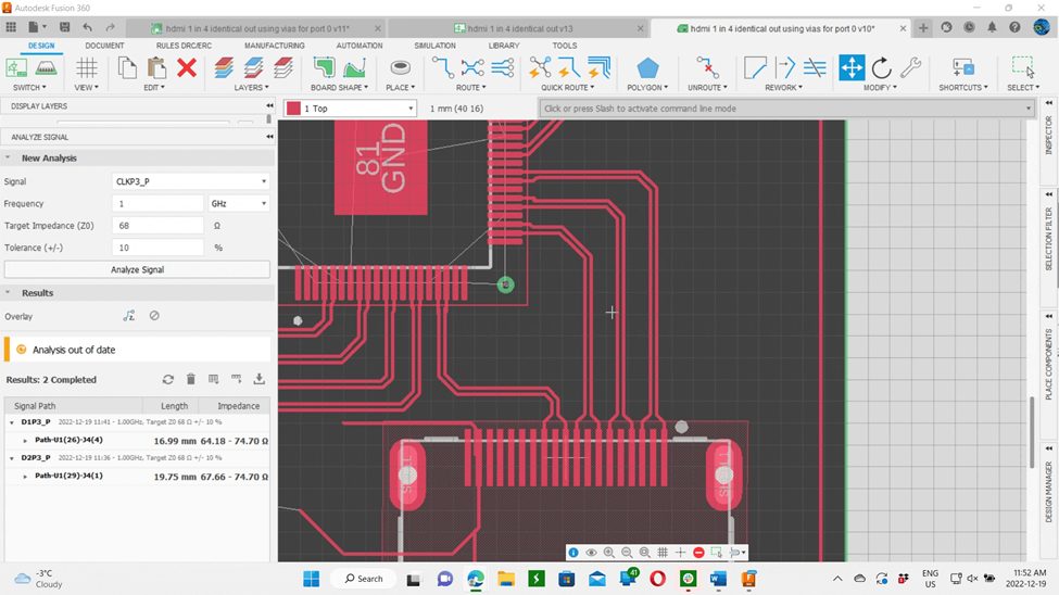
Either way, Fusion 360 Electronics with the SI extension can calculate the time differences and lengths of signal traces.
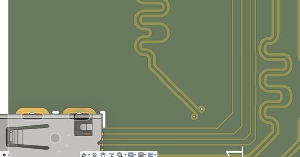
Meandering
Meandering is a technique to lengthen traces so that the skew is within the required range. This is often a serpentine trace that winds back and forth to obtain the required length. Its use is on individual single traces or on differential traces.
Fusion 360 can meander individual traces and differential traces to a specified length and will even adjust the intra-pair length to ensure a differential pair has the same length.
When dealing with high-speed designs you will need to ensure that traces meet skew specifications. Often you define maximum skew in terms of the maximum allowable by a connecting cable. This means the PCB layout designer needs to make the skew introduced by traces as small as possible as it will add to the skew the cable provides.
Fusion 360 enables the PCB designer to equalize trace lengths to specified lengths ensuring the least amount of skew between signals.
Trace width and high-speed PCB designs
Download a free trial of the Fusion 360 Signal Integrity Extension today.