This article will cover what Electromagnetic Interference (EMI) is, what causes it, why you should avoid it, and what steps you can take to protect your electronics.
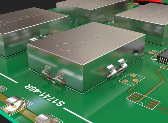
Critical circuits are covered with metal shields in EMI shielding to protect them from radiation and EMI absorption. Let’s walk through why it matters for PCB design!
Important Note: EMI is one of the main reasons why PCB designs need to be re-started. It is estimated that 50% of initial PCB designs fail because they emit or are susceptible to unwanted EMI.
What causes Electromagnetic Interference (EMI) in Your Circuit Board?
Have you ever noticed how your speakers emit static when someone’s telephone rings while you listen to the radio? This is because your radio signal is interfering with the mobile signal coming from the cell tower.
When one signal’s source interferes with another signal, it is known as electromagnetic interference or EMI. It goes beyond just interfering with your favorite song and is not a benign form of interference.
Through conduction, electrostatic coupling, or induction, EMI can harm circuits. As a result, EMI exposure might cause a gadget to malfunction or not function as planned.
Why Is Avoiding Electromagnetic Interference Important?
Many different types of electromagnetic interference sources surround us.
- Source: Electronic circuits are where human-made EMI is produced. On the other hand, environmental elements like cosmic noise and lightning can cause naturally occurring EMI.
- Duration: Continuous interference is an EMI source that continuously generates a signal, which primarily takes the form of background noise. Impulse interference is sporadic and typically results from lightning, switching systems, and other irregular causes.
- Bandwidth: Oscillators and transmitters may cause interference to radio-frequency narrowband transmissions; however, this interference only occasionally affects certain portions of the spectrum. High-data signals like TV are impacted by broadband interference, which can come from various sources such as solar noise and arc welders.
How to Reduce Electromagnetic Interference (EMI) in Your PCB Designs?
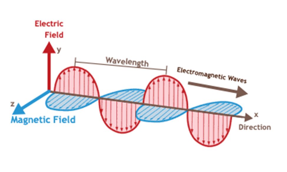
When electromagnetic energy interferes with an electronic device’s signaling through radiation or induction, it is known as electromagnetic interference (EMI). EMI is all about us, from the static on your radio to the buzz you hear while using a cell phone close to audio equipment.

All you need to produce EMI is energy and an antenna. A dipole placed across an energy source is required to create an EMI-radiating antenna. In essence, electronic gadgets are electromagnetically active boards.
Furthermore, you must meet EMI/EMC rules and requirements before your product can be put on the market since EMI radiation can affect essential electronics in the environment around us, such as the gears on an airplane. Let’s explore the typical methods you might use to lower EMI in your PCB designs.
Ground Plane: Your First Line of Defense

Your board’s circuits need at least a floating ground in order to function. The ground plane serves as your first line of defense against the noise that EMI produces. The ground plane is comparable to a sizable water basin in the textbook water analogy, where the current in your circuit is like water in a network of water pipes.
There are ripples made as the water enters the basin. A huge basin can quickly absorb such ripples, but if the basin were smaller, it would stick around for an extended time and bounce off the walls.
What Is the Purpose of the Ground Plane in Your Circuit Board?
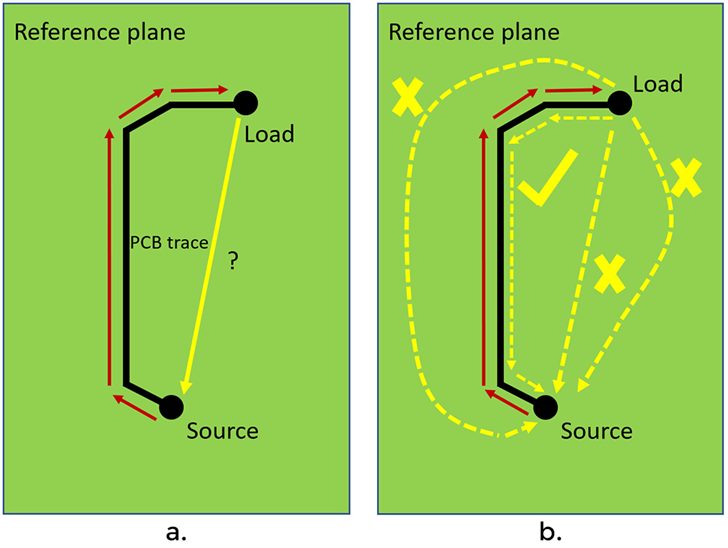
The purpose of the ground plane in a PCB is to supply a 0-volt reference line to the power supply ground terminal for a circuit’s return path. Contrary to the basin, the board can turn into an antenna when “ripples” are formed since noise is made, dipoles can develop, and the board itself can become noisy.

How well you use the ground plane is the first step in lowering EMI across the board. For this reason, the ground plane, the copper foil layer on your PCB, occupies as much of the board’s cross-sectional area as possible. Standard best practices for EMI with ground reduction include:
- You can use a multi-layer board. If you add another layer, you may have more alternatives for handling high-speed traces on your board. If crosstalk being generated by differential pairs? Send them via an inner layer to reduce noise.
- Split ground planes must be used with caution. Split ground planes can behave as slot antennas and radiate; therefore, if you do that, make sure you have a good reason, such as separating analog and digital grounds, to prevent noise coupling.
- Connect split ground planes just at one location. You will produce more loops and emit more EMI from your design if you have more common ground connections.
- Connect the ground plane to any bypass or decoupling capacitors. If your design includes any of these components, you can reduce the radiation by connecting them to the ground to shorten the current return route, which will also reduce the size of the loop. Avoid capacitive coupling by connecting a bypass capacitor between a related ground plane and a power plane.
Trace Layout: Conductive Paths on a Board
It only takes a bend or cross to transform traces, which are conductive lines on a board that contains flowing electrons while a circuit is operational, into fully radiating antennas.

The following are the most typical recommended practices for trace layout that you should be aware of:
- Steer clear of acute right-angle curves. Right angles can be rounded to reduce the impact. In the 45° corner region, capacitance rises, altering the characteristic impedance and causing reflections.
- Shorten return paths
- Place differential traces as near together as possible. Due to the increased coupling factor, influenced noise is moved into the common mode, where it is less disruptive to a differential input stage.
- Use vias responsibly. Vias enables you to use numerous layers in your boards while routing. Designers must consider the effects of their inductance and capacitance, and reflections can result from a change in characteristic impedance.
- Prevent differential traces from using vias. Use the two vias’ shared oval anti-pad if necessary to reduce parasitic capacitance.
How Can You Arrange the Components in Circuit Boards?
The building blocks of all electronic designs are based on the components used from the library. Better PCB design can result from taking into account how each component can affect EMI. Component layout best practices include:
- Maintain a clear separation between analog and digital circuits. Similar to the traces, keeping AC and DC circuits separate is best to prevent crosstalk and other problems. Several effective strategies include shielding, utilizing numerous layers, and using different grounds.
- Isolate components at a fast speed. The EMI increases with component speed and size. Use shielding and filtering to reduce the EMI impacts that high-frequency clocks in CPUs and GPUs naturally cause.
Electromagnetic Interference (EMI) Shielding: with a Faraday cage

It’s acceptable that some components may inevitably produce EMI. A Faraday cage, which is a container built of conductive materials thick enough to prevent RF waves, can be used to protect them. In reality, we employ boxes made of metal or conductive foam instead of the ideal Faraday cage, which would be a conductive enclosure without any gaps.
You Can Reduce Power Rail Noise Using Decoupling Capacitor
High-frequency current switches made by ICs during operation cause switching noise in the power rails and IC-connected traces. If this noise is not reduced, it will cause radiated emissions and hence EMI. Placing the decoupling capacitors next to the IC power pins is one way to decrease noise on the power rails.
Additionally, directly grounding the capacitors to the ground planes. Power noise can also be decreased using power planes rather than power traces.
Testing Electromagnetic Interference (EMI) in Your PCB Design
The electromagnetic emission in your electrical system can be simulated using several modeling techniques. Computer simulation has proven efficient and provides results faster than waiting for the physical board to arrive and having the equipment for testing.

The computer simulation is done using an integration technique to precisely analyze essential parameters. Follow these steps to detect electromagnetic emissions in your electronic system:
- In high-voltage applications, the frequency response of the common-mode current is measured using finite difference time domain modeling.
- Factors like current-mode antenna impedance and the distributed circuit constant are considered when evaluating the common-mode current.
- The electrical coupling between the ground and power planes will also impact the common-mode current.
Using a sophisticated tool and our own suggested model, we measure the frequency response of electromagnetic emission from the strapline structure. We wanted to provide you with insights and design guidelines to keep your circuit secure because we recognize the value of keeping EMI out.
Now You Can Easily Reduce (Electromagnetic Interference) EMI in Your Future PCB Designs
When you lay out the traces and vias on your board, it’s far too simple to generate an antenna unintentionally. You can see why EMI reduction is more important than ever before when you combine that with the continuously increasing demand for greater clock speeds.
In summary, it’s always better to design your board with EMI in mind rather than risk redesigning, but you need to be clear about what EMI rules will apply to your design and how.
In addition, the ability to analyze with tools built into PCB CAD can significantly reduce the risk of EMI violations after the board is manufactured; but ensure that the design rule checkers are based on well-documented and proven EMI principles and interpretations.
Frequently Asked Questions
Why should you pay attention to EMI issues while designing a PCB board?
EMI’s issues are of most significant concern to designers of circuit boards for home appliances such as toasters, refrigerators, and washing machines that integrate multiple devices that support wireless IoT connectivity. For high production volumes, PCB redesign can delay product release. Even worse, a product recall can cause severe damage to a company’s reputation and finances.
How to suppress noise sources on a printed circuit board?
- Try to use the lowest possible synchronization frequencies, and increase the rise times of the fronts to the maximum.
- Try to locate the timing circuits in the center of the printed circuit board, except when the clock signal must leave the board.
- Layout the resonator crystals close on the PCB as close as possible to the input pins of the load and ground them.
- Make all printed conductors of the synchronization circuit as short as possible.
- Place I/O drivers near the places where signals enter or leave the board
- Filter all signals coming to the board.
Why should you analyze electromagnetic radiation modeling?
As with EMI’s design code checkers, the value of the results will depend on how well the digital representation matches the actual board and its behavior and, of course, how good the various equations underpinning software algorithms for the analysis of electromagnetic radiation are.
Ready to get started with electronics design in Fusion 360? Download a free trial of the Fusion 360 Signal Integrity Extension today: