
Have you ever hit your shin on, let’s say, a coffee table that has sharp corners? Chances are you have, but probably not very often. Oh, you may be a klutz and run into things all the time, but chances are the edge of what you kick isn’t actually sharp, that is at a 90* angle (it just feels like it is). Most things in our day-to-day lives have at least a slightly rounded edge.
Not only is it more aesthetically pleasing, but it’s usually practical too. It could be to eliminate sharp edges or corners that could be vulnerable to stress concentrations. Perhaps they’re included to improve functionality or facilitate design manufacturing processes.
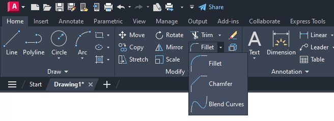
In the world of drafting, these rounded edges are called fillets. Here’s how to use fillet in AutoCAD.
Fillet’s First Cousin – Chamfer
Maybe the edge of that coffee table you kicked wasn’t rounded. It was straight but angled like a bevel. Again, in the world of drafting, that’s called a chamfer and is applied for many of the same reasons that a fillet would be. In general, they work pretty much the same.
Today, I’ll look at how these two AutoCAD tools work. Since this is a tips blog, I’ll offer a couple of other uses for these commands as well.
When you run either Fillet or Chamfer, you’ll have plenty of options. Five for fillet and seven for chamfer, along with some sub-options. But since they’re related as cousins, there’s a lot of overlap. The most important for Fillet is “Radius.” Use it to set the radius to use. Pretty simple. It will keep that value until you change it.
Chamfer needs two distances. They can be the same (a 45* angle), or they can be different. That option is called “Distance,” and it will prompt you for the first and second distance. You can also specify an Angle, which sets the Chamfer distance from the intersecting point of the selected objects and the XY angle from the first object or line segment.
And, with the Chamfer command, you can set in advance which mode to use (distance or angle) with the Method option.

What Fillet and Chamfer Have in Common
Both commands have an undo option. That should be self-explanatory. Both have a trim option, which controls whether the selected objects are trimmed to meet the endpoints of the fillet or chamfer line.
The multiple option allows for the command’s application of more than one set of objects. Both have a polyline option, which inserts a chamfer or fillet at each vertex of a 2D polyline where two straight line segments meet. They become new segments of the polyline unless the trim option is set to no trim.
So, as you can see, they have a lot in common. Oh, plus one more thing. Once your settings are done, both tools are easy to use. It’s just a matter of picking two lines, or if you’re using the polyline option, you’ll just select the polyline.
Time for Tips
You can use these cousin commands for a few other things than what they’re intended for. Both can be used as a cleanup tool. What if you had some corners that don’t quite meet up, but they should? You can use either Fillet or Chamfer to join them.
You could set Fillet’s radius to 0 and both of Chamfer’s distances to 0 and each would join your lines. But then you have to go back and reset them, and that sounds like a lot of extra picks and clicks to me. However, there’s a cool keyboard shortcut you can use. Regardless of what the radius or distances are set to, just hold down the shift key and select both objects. Badda-bing! You’ve joined your lines and saved lots of clicks.

I’ve got one more for you. What if you have parallel lines? First of all, you might be asking why you’d be filleting or chamfering parallel lines. Stick with me here. First chamfer – other than being an offhand way to check for parallelism, won’t do you much good.

In this case, the Fillet command is the smarter cousin.
Just run the Fillet command, then select both lines. You don’t even have to set the radius to zero or hold down the shift key, so your existing value stays set. A connecting arc will be drawn between the two parallel lines based on which side of the first line is selected. Pop the spacebar to start the command again and select the other ends and you have yourself a slot.
Better yet, use those steps to create a script or even a pretty simple lisp routine, call it “slot”, and you’ve created your own new AutoCAD command.
Amaze your friends at parties and gatherings by showing them an AutoCAD command that they don’t have! I may have mentioned before that I need to get out more.


Add comment
There are no comments